Machining Plastics vs Metals: Challenges and Solutions
Plastics don't machine like metals. Learn the critical differences in tooling, speeds, workholding, and thermal management that determine success when machining engineering plastics.
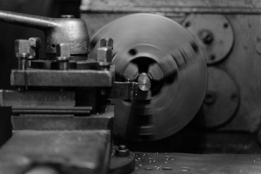
Engineers comfortable machining aluminum or steel often struggle when their first plastic job arrives. The tooling that works perfectly on 6061 leaves a melted mess in acetal. The feeds and speeds that produce beautiful chips in brass create nothing but plastic dust in UHMW.
Plastics demand a fundamentally different approach. This guide explains why—and how to get it right.
Why Plastics Are Different
Three material properties drive most machining differences between plastics and metals.
Thermal Conductivity
Plastics conduct heat 100-300x slower than metals. When you machine aluminum, heat transfers into the workpiece and spreads throughout the material, eventually dissipating through the chip as it’s carried away. When you machine plastic, heat stays right where it’s generated—at the tool tip. This concentration of thermal energy at the cutting zone dominates plastic machining strategy. Parameters that work fine for the first few seconds may cause melting within minutes as heat accumulates faster than it can escape.
Thermal Expansion
Plastics expand 5-10x more than metals per degree of temperature change.
| Material | Thermal Expansion (in/in/°F) |
|---|---|
| Aluminum | 13 × 10⁻⁶ |
| Steel | 7 × 10⁻⁶ |
| Acetal | 50 × 10⁻⁶ |
| UHMW | 100 × 10⁻⁶ |
| Nylon | 45 × 10⁻⁶ |
A plastic part that measures within tolerance while still warm from machining may be out of specification once it cools to room temperature. Conversely, a cold morning in an unheated shop changes starting dimensions enough to throw off the first parts of the day.
Elastic Modulus
Plastics are 10-100x less rigid than metals.
| Material | Elastic Modulus (psi) |
|---|---|
| Steel | 30,000,000 |
| Aluminum | 10,000,000 |
| Acetal | 400,000 |
| UHMW | 100,000 |
| PEEK | 500,000 |
This low stiffness means plastics deflect under cutting forces far more than metals do. Thin walls flex away from the tool during the cut. Parts spring back after clamping is released, changing dimensions that looked perfect before unclamping. Tolerances achievable in metal often aren’t achievable in plastic without special techniques to manage deflection.
Tooling for Plastics
Metal-cutting tools can work but rarely produce optimal results in plastics. The geometry that works for steel creates too much friction and generates excessive heat in plastic.
Geometry Requirements
Successful plastic machining starts with positive rake angles in the 15-20 degree range. This aggressive angle reduces cutting forces and heat generation significantly. Metal-cutting tools often have neutral or negative rake designed for material strength, not heat sensitivity. Large relief angles of 10-15 degrees prevent rubbing behind the cutting edge, which is critical because rubbing generates heat without removing any material. Sharp edges matter more in plastics than in most metals—dull tools push rather than cut, creating friction heat that melts rather than chips. Finally, polished flutes reduce chip adhesion, particularly important for gummy materials like UHMW that love to stick to rough surfaces.
Tool Types
O-flute router bits represent the gold standard for plastic machining. Designed specifically for plastics, their single-flute design maximizes chip clearance and prevents the re-cutting that causes heat buildup. Plastic-specific end mills available from specialty suppliers offer a two-flute design with modified geometry optimized for polymers. Standard carbide end mills can work for occasional plastic jobs, but expect slower speeds and more attention to chip evacuation. HSS tools remain acceptable for low-volume work since they can be sharpened to finer edges than carbide.
Coatings
For most plastics, uncoated tools work best. Coatings like TiN or TiAlN actually increase friction and can cause chip adhesion—the opposite of their benefit in metal cutting. The exception is abrasive fillers: glass-filled nylon and carbon-filled PEEK wear uncoated tools rapidly, justifying diamond-like coatings despite their higher cost.
Speeds and Feeds
The guiding principle for plastic machining is simple: keep chips moving, and keep heat moving with them.
Surface Speed
Most plastics machine well at 500-1000 SFM—faster than steel but similar to aluminum.
| Material | SFM Range |
|---|---|
| Acetal | 500-1000 |
| UHMW | 500-1000 |
| Nylon | 300-600 |
| PEEK | 200-400 |
| PTFE | 300-500 |
| Polycarbonate | 400-800 |
Higher surface speed is generally better unless melting occurs. The goal is to get through the cut before heat accumulates to problematic levels.
Feed Rate
This is where plastic machining diverges most dramatically from metals. You need to feed faster than intuition suggests.
High feed rates keep chips large enough to carry heat away effectively, prevent dwelling where the tool sits in one place generating heat, and reduce total machining time so there’s less opportunity for heat to accumulate in the workpiece. Low feed rates cause the opposite problems: fine chips or dust that carry no heat away, melting and re-welding of material behind the tool, glazed surfaces that indicate thermal damage, and poor surface finish.
If you’re making dust instead of chips, increase the feed rate immediately.
Chip Load Recommendations
| Material | Chip Load (in/tooth) |
|---|---|
| Acetal | 0.005-0.010 |
| UHMW | 0.008-0.015 |
| Nylon | 0.004-0.008 |
| PEEK | 0.003-0.006 |
| Polycarbonate | 0.004-0.008 |
Heat Management Strategies
Chip Evacuation
Chip evacuation serves as the primary heat removal mechanism in plastic machining. Every chip that leaves the cutting zone carries heat with it, while every chip that stays re-cuts and adds heat. Use tools with large flute volume to give chips somewhere to go. Keep flutes clear so chips don’t pack in and re-cut. Through-spindle air blast pushes chips out continuously, and vacuum collection during long operations keeps the work area clean while removing heat-laden material.
Air Cooling
Compressed air directed at the cutting zone provides cooling without introducing moisture concerns. The airflow cools the cutting zone, blows chips clear of the cut, and avoids the material absorption issues that liquid coolants can cause. Air cooling works for most plastics except in heavy cutting situations where more aggressive cooling becomes necessary.
Liquid Coolant
Use liquid coolant sparingly and only when truly necessary. Non-hygroscopic plastics like acetal, UHMW, PTFE, and polyethylene can tolerate water-based coolants for heavy roughing or large material removal operations. However, avoid coolant entirely on hygroscopic materials: nylon absorbs moisture and changes dimensions, unfilled PEEK experiences property changes from moisture exposure, and any part requiring tight tolerances on hygroscopic material will suffer dimensional instability. When using coolant, choose water-soluble types and dry parts thoroughly before inspection.
Intermittent Cutting
For extended operations, consider strategies that allow cooling between cuts. Pecking cycles that retract periodically let heat dissipate. Breaking long cuts into segments achieves the same effect. Allowing time for the part to stabilize between roughing and finishing passes prevents the accumulated heat from roughing operations from affecting finish dimensions.
Workholding Challenges
Clamping Pressure
Plastics deform elastically under clamping force in a way that metals don’t. The sequence of problems is predictable: the part is clamped and deforms slightly under pressure, the part is machined to dimension while deformed, the clamps are released, the part springs back toward its original shape, and the dimension is now wrong.
The solution involves using minimum necessary clamping force, distributing force across multiple light clamps rather than concentrating it in a few heavy clamps, using fixtures that spread force evenly across the part, and employing soft jaws contoured to match part geometry.
Deflection During Cutting
Low elastic modulus means parts flex away from the tool during cutting. Thin walls need internal support or must be machined from both sides with spring passes to achieve accuracy. Long spans require support fixtures, or you can use climb milling to push the workpiece against a support surface. Deep pockets benefit from different toolpath strategies that manage cutting forces to reduce deflection.
Surface Marking
Knurled vise jaws leave permanent impressions in plastic parts. Finished surfaces require soft jaws made from aluminum, plastic, or rubber-faced material. Paper or thin shim stock between the jaw and part works for quick jobs. Better yet, design fixtures that clamp on areas that will be machined away in subsequent operations.
Vacuum Fixtures
Vacuum fixturing excels for sheet materials. The holding force is uniform and low-stress, leaving no jaw marks. Setup becomes fast and repeatable for multiple parts. The main requirement is a sealed surface, either through gaskets or a spoilboard that conforms to the part.
Material-Specific Tips
Acetal (Delrin)
Acetal ranks among the easiest plastics to machine. It produces excellent chips, holds dimensions well, and tolerates aggressive parameters. Light coolant is acceptable if needed for chip evacuation. The main caution is watching for chips welding back to the surface if feed rates drop too low.
UHMW
UHMW is extremely gummy—chips tend to wrap around tools rather than clearing. Single-flute tools work better than multi-flute designs because they provide maximum chip clearance. Very sharp edges are essential to achieve a clean cut rather than a pushed, smeared surface. Air blast helps chip evacuation significantly. Expect difficulty holding tight tolerances due to UHMW’s high thermal expansion coefficient.
Nylon
Nylon is hygroscopic, meaning moisture changes dimensions significantly. See our engineering plastics guide for property details. Never use water-based coolant on nylon. Condition the material to stable moisture content before machining by storing it in controlled conditions. Machine dry and measure at stable temperature and humidity. Allow equilibration time before final inspection, as the part needs to reach the same moisture level as its operating environment.
PEEK
PEEK offers the highest performance but presents the most challenges. Material costs make mistakes expensive. Use lower speeds than other plastics, as PEEK generates more heat during cutting. Sharp tools are essential because the material work hardens slightly. Avoid moisture on unfilled grades since it affects mechanical properties. Glass or carbon filled grades wear tools rapidly, justifying diamond coatings despite their cost.
PTFE (Teflon)
PTFE is very soft and prone to cold flow and deformation under any sustained load. Use light cuts only, as aggressive parameters cause the material to flow rather than chip. Support the material fully to prevent movement during cutting. Holding tolerance is difficult due to the material’s tendency to deform. Thread engagement is poor because the material flows out of the way—use metal inserts for any threaded connections.
Dimensional Stability
For tight tolerances, process stability matters as much as machine capability.
Temperature Control
Equilibrate material to stable temperature before machining by storing material in a temperature-controlled area. Allow time for thick sections to reach thermal equilibrium throughout. Measure at consistent temperature and document the temperature at inspection so that any discrepancies can be traced to thermal effects.
Stress Relief
Internal stresses from extrusion or previous machining can cause warpage that appears after final machining. For tight-tolerance work, rough machine oversize, stress relieve by annealing per material specification, then finish machine to final dimension.
Moisture Equilibration
For hygroscopic materials, understand the target environment’s moisture content. Either condition the material to that moisture level before machining, or machine dry and allow equilibration before inspection. The part will change dimensions as it absorbs or releases moisture to match its environment.
Tolerance Expectations
Standard machining tolerances for plastics differ from metals due to the material properties discussed above. See our CNC tolerances guide for general reference.
| Feature | Typical Plastic Tolerance |
|---|---|
| General dimensions | ±0.005” |
| Precision dimensions | ±0.002” |
| Very tight (with process control) | ±0.001” |
Achieving metal-like tolerances requires careful process control, environmental stability, and appropriate material selection. Not every plastic can hold tight tolerances even with perfect technique.
Working With NextGen Components
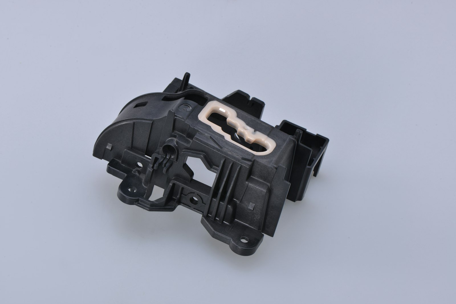
We machine engineering plastics alongside metals, understanding the different requirements each demands. We source materials from qualified suppliers with full traceability, develop process parameters specific to each material family, maintain environmental controls for dimensional stability, and provide documentation meeting customer requirements.
Questions about plastic machining capabilities or material selection? Contact our team to discuss your application.
Ready to Start Your Project?
Contact us to discuss your material and manufacturing needs.
Get a Quote